This is the second round of FEA of Pressure Vessel Nozzle but should have been done before my previous post, so I have called it Zeroth Pass.
When i posted my FEA results that I obtained, I was asked to first carry out simple shell FEA of Pressure with Brick element.
The model is shown below
Zoomed in Version of the mesh to show Brick elements in thickness is shown below.
If you are interested in my previous FEA report and want to download a PDF file of the report, please Click here
I modeled the same geometry that i had modeled in my previous exercise without the nozzle.
I ran two analysis on the geometry.
- With Bottom face having only DZ-0 boundary condition (to model ideal case)
- With Bottom face having DX, DY and DZ = 0 boundary condition (to model the case similar to what i had done in my FEA report)
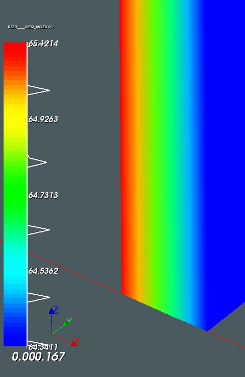
VonMises Stresses for Analysis 1 is shown below
And here is the Zoomed in Version of the above plot that shows the edge of the PV.
As can be seen the Stresses are averaging 65MPa.
For Analysis 2, the bottom Face was Fixed DX, DY and DZ = 0, so the VonMises Stresses are
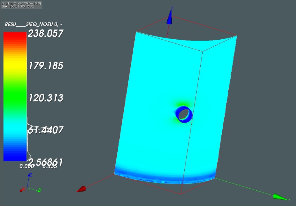
As can be seen, there is stress profile near the bottom area where the face is rigidly fixed. Far from the rigid face, the stresses average around 65MPa and this matches the plot of my FEA report with the Nozzle (Shown below for comparison only) away from any discontinuities.
The zoomed in version of VonMises Stress for the geometry without nozzle is shown below
Hand Calculation for this can be downloaded by clicking HERE


